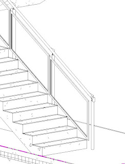
Climbing those stairs
Some how over the last year I have avoided creating any, slightly complex,stairs. The thing I always found bewildering was creating the railing and balusters. I remember trying to create a stair with a glass panel and was annoyed that the panels would not automatically stretch to fit. So ended up creating one single glass panel as a rail using the rail tool.
I have now had to face up to getting my head round the stairs. After reading the fantastic notes by Phil Read, I stretched my fingers, rolled up my sleeves, and began to build my stairs.
The stairs that I need to build are not complex, each stair is made up of concrete stair, with a number of balusters fixed to the side of the stairs, the baluster has an angled head to carry the rail, between these balusters are glass panels in a steel frame.
After looking through stair examples I decided to go with an in-the-box stair/rail solution.
Building the components
- I used the baluster family template to create my baluster. To avoid some stretching issues the top of the baluster was a generic model nested in:
- Built the end of the rail (it had a turn down at the end) as a baluster family. I made it more difficult for myself by modeling the horizontal as well as the vertical part of the turn down - getting this to fit correctly with the angled rail was a nightmare - will not do that again.
- Built the glass panel in the steel frame with the baluster panel template.


Get those rails in order
The rail is a line based family. Each segment of that line is the centre line of the rail and follows the angle of the item that it is proportionally on, therefore you create a separate segment for a landing, and stair rise, the rail also has properties that can deviate from the default setting.
- I set out my rail on the edge of the stair and created a new segment for each section of pipe. and then offset this line to the designated position - I could have set this offset in my rail properties.
- The rail at the landing was 100mm higher than on the stairs, I edited these segments to be 100mm higher than the default.
Setting out the stairs
Revit uses a text/list based approach to placing balusters on to a rail. Although it is very powerful, a graphical approach would make it more intuitive and give a bit more control. To save ripping your hair out, I suggest you sketch out the setting out of the panels and balusters before adding them to the rail.
- Sketched out my setting out drawing, worked out all the different panel lengths that I needed.
- Created all the different panel types that I needed.
- I defined my starter baluster as the rail end.
- I then started to define my baluster pattern - using the measurements from my setting out plan - remembering that the baluster's mid point is it's insertion point.
- Getting round corners was slightly tricky.
- At one point I reduced the length of my rail and all my panels disappeared. If Revit does not have enough rail to hang all of the baluster pattern onto, it will not show any of it.
Once you get your head around the limitations of the stair tool - for example it doesn't highlight the baluster you are editing.
The other thing you need to understand is that the balusters in the rail tool are parametric but limited, heights can automatically change, offsets can be defined as can positioning, but what you can not control within the rail tool is the width of the balusters, you have to create different types outside of the rail tool environment.
Future notes
The Revit Stair tool has evolved in 2013 into a much better tool, but still not as graphical as you think it should be - something similar to the Curtain Walling tool perhaps.


No comments:
Post a Comment