Thursday, 4 July 2013

3D Room Section

One of the things that I liked about ArchiCAD was the ability to quickly create a 3d room section.

To achieve this in Revit:


  • I create a Callout (View tab; Create panel; Callout).
  • Open a default 3D view.
  • Right-click on the View Cube. 
  • Select Orient to View; Floor Plans, and choose the Callout view you just made. Your 3D view will automatically have a Section Box that matches the Crop Region of the Callout! 

This works really well unless you have a large number of views that you have to scroll through to find the one that you just created.

Another way - is the free COINS Auto-Section Box add-in available on Autodesk Exchange. Install the add-in, restart Revit, select a few objects then click the button. It will create a section box around those objects in the selected 3D view - very easy!

Download at:

Autodesk Exchange Apps


Revit Content

This has been in my drafts - for nearly a year, so the new is pushing it a bit.

There is a new site competing with AutoDeskSeek, NationalBimLibrary, and BIMStore for supplying free manufacturer’s 3d content. Unlike BimStore and AutoDeskSeek, BIMOBJECT.COM provides models not only in native AutoDesk formats (dwg, 3ds, rvt, rfa), but also in SketchUp, ArchiCAD, AllPlan, IFC, etc. Content seems to be European, product descriptions are not always in English.


Ceiling Height in Room Data Tag

Adding ceiling height to a Room tag

On a project we needed to include the ceiling height in our Revit generated Room Data Sheet. Our Room Data Sheet is a glorified room tag.

I couldn't find anyway of doing this automatically, I presume that it would be very difficult as a room could have different ceiling heights.

The solution that we used was using a plugin from White Feet. The addin allows you to populate a parameter value from a calculated value - we created a Shared Parameter called CeilingHeight which used the calculated value of  a Room's Volume/Area and parameters.

For this to work you need to have Volume computation turned on, and make sure that the room's Upperlimit is set higher than your ceiling height, if not Revit uses the Upperlimit value. The default Upperlimit is 4m, worth checking if you have an Atrium or double height room:

White feet

White feet create a set of great addin tools for Revit. The one we are going to use is the Parameter Toolshttp://www.whitefeet.com/Tools/.

You will also have to create a Shared Parameter called CeilingHeight. This will be added to the template in due course.

Once you have installed the plugin, select Parameter Tools and then select Math Calculation:

 
In the Math Calculation window select the following (CeilingHeight is the Shared Parameter that you have created):


Note: the CeilingHeight value will not automatically update, you will need to run this before each issue to make sure that it contains the right data.


Monday, 14 January 2013

Revit Cloud Rendering

At the moment we are on subscription and use AutoDesk's render cloud for our Revit renders. Interested to see that there is a competitor: https://limitlesscomputing.com/solutions/LimitlessRender

They also do Cloud rendering of walkthroughs. $999 for 300 frames (1920x1080) with upto 25 lights. At 24 frames per second, that's about £80 per second. Anyone used them?

Monday, 9 July 2012

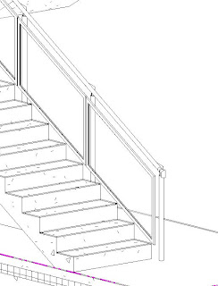
Climbing those stairs

Climbing those stairs

Some how over the last year I have avoided creating any, slightly complex,stairs. The thing I always found bewildering was creating the railing and balusters. I remember trying to create a stair with a glass panel and was annoyed that the panels would not automatically stretch to fit. So ended up creating one single glass panel as a rail using the rail tool.
I have now had to face up to getting my head round the stairs. After reading the fantastic notes by Phil Read, I stretched my fingers, rolled up my sleeves, and began to build my stairs.
The stairs that I need to build are not complex, each stair is made up of concrete stair, with a number of balusters fixed to the side of the stairs, the baluster has an angled head to carry the rail, between these balusters are glass panels in a steel frame.
After looking through stair examples I decided to go with an in-the-box stair/rail solution.

Building the components

  • I used the baluster family template to create my baluster.  To avoid some stretching issues the top of the baluster was a generic model nested in:
  • Built the end of the rail (it had a turn down at the end) as a baluster family. I made it more difficult for myself by modeling the horizontal as well as the vertical part of the turn down - getting this to fit  correctly with the angled rail was a nightmare - will not do that again.
  • Built the glass panel in the steel frame with the baluster panel template
                       

Get those rails in order

The rail is a line based family. Each segment of that line is the centre line of the rail and follows the angle of the item that it is proportionally on, therefore you create a separate segment for a landing, and stair rise, the rail also has properties that can deviate from the default setting.
  • I set out my rail on the edge of the stair and created a new segment for each section of pipe. and then offset this line to the designated position - I could have set this offset in my rail properties.
  • The rail at the landing was 100mm higher than on the stairs, I edited these segments to be 100mm higher than the default.

Setting out the stairs

Revit uses a text/list based approach to placing balusters on to a rail. Although it is very powerful, a graphical approach would make it more intuitive and give a bit more control. To save ripping your hair out, I suggest you sketch out the setting out of the panels and balusters before adding them to the rail.
  • Sketched out my setting out drawing, worked out all the different panel lengths that I needed.
  • Created all the different panel types that I needed.
  • I defined my starter baluster as the rail end.
  • I then started to define my baluster pattern - using the measurements from my setting out plan - remembering that the baluster's mid point is it's insertion point.
  • Getting round corners was slightly tricky.
  • At one point I reduced the length of my rail and all my panels disappeared. If Revit does not have enough rail to hang all of the baluster pattern onto, it will not show any of it.
Once you get your head around the limitations of the stair tool - for example it doesn't highlight the baluster you are editing.
The other thing you need to understand is that the balusters in the rail tool are parametric but limited, heights can automatically change, offsets can be defined as can positioning, but what you can not control within the rail tool is the width of the balusters, you have to create different types outside of the rail tool environment.

Future notes

The Revit Stair tool has evolved in 2013 into a much better tool, but still not as graphical as you think it should be - something similar to the Curtain Walling tool perhaps.

Circular chain of references


Circular chain of references

Circular Chain of References are, putting it mildly, frustrating. Once you get the message it can seem as though your model has been paralyzed.
There is a solution. First thing to do is to try and work out where the chain is.
An example of this was on a project where trying to delete any thing connected to the floor slab would come up with the Circular Chain of References error message. It was obvious that the problem was to do with the floor slab but we couldn't edit or delete it. 
  • In a 3d view I hid the walls and tried to delete each floor seperatly to see which of the floor/roof slabs where causing the circular reference.
  • The Ground Floor slab was referencing the First floor slab, this was referencing the Roof slab and the Roof slab was referencing the  First floor slab.
  • I selected the two referencing elements together and pressed delete. I did get a warning so I clicked Expand and selected two elements that had to go (door and a wall) and clicked Delete Instances.
In this instance it was decided to redraw the elements, although we could have copied and pasted from an older model file that did not have this problem.

Tuesday, 26 June 2012

Using sat files

Received an enormous sat file from the steel fabricators today 225mb. Decided to link it into our Revit model - slow to load in and made the model unworkable. The answer was not to link to the sat file, but to import the sat file into a clean Revit project, save that and then link that Revit project into our model. The size of the project with the sat file imported into it was 30mb - a massive reduction.